Design of the Upper Cover of a Household Air Conditioner Remote Control
On this page
Abstract: The upper cover of a remote control is an essential component of plastic molded remote controls. On one hand, it is aesthetically pleasing and user-friendly. On the other hand, it effectively protects electrical components like batteries. To meet the demand for fast, efficient, and large-scale production, reverse engineering technology can shorten the development cycle of molds for similar products, significantly enhancing production efficiency. This design focuses on the upper cover of a specific household air conditioner remote control, using a 3D scanner for point cloud scanning and reverse engineering to obtain the upper cover model, followed by mold design.
Preface
Molds, often referred to as the "mother of industry," are also known as industrial amplifiers. Through reverse engineering, the mold production cycle for similar products can be significantly shortened, thereby improving production efficiency. This paper presents reverse engineering of the upper cover of a specific household air conditioner remote control and designs the corresponding injection mold.
1. Product Analysis
The product dimensions are 136 mm long, 36.5 mm wide, approximately 10 mm high, with a volume of 5,248.63 mm² and a mass of 13.8 g. The outer surface is smooth, featuring rounded corners and internal cross-reinforcement ribs. The product is classified as a small plastic item. When designing the mold, multiple cavities can be used in one mold to improve production efficiency. The actual product and its dimensions are shown in Figures 1 and 2.
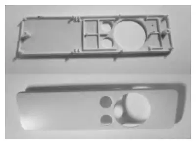
Figure 1 The Air Conditioner Remote Control
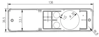
Figure 2 Product Dimensions
The plastic part is made from PC, with an annual output of 500,000 pieces, a surface roughness of Ra=0.8, general accuracy requirements, and an accuracy level of MT3. The performance parameters of PC are shown in Table 1.
Table 1 Material performance parameters

Figure 1 The Air Conditioner Remote Control

Figure 2 Product Dimensions
The plastic part is made from PC, with an annual output of 500,000 pieces, a surface roughness of Ra=0.8, general accuracy requirements, and an accuracy level of MT3. The performance parameters of PC are shown in Table 1.
Table 1 Material performance parameters
| Parameters | Parameter Value |
| Density (g/cm³) | 1.2 |
| Reflectivity (%) | 89 |
| Impact Strength (J/m) | 100 |
| Melting Point (°C) | 220–230 |
| Shrinkage (%) | 0.5–0.7 |
| Transmittance (%) | 89 |
| Tensile Strength (MPa) | ≥100 |
| Flexural Strength (MPa) | ≥60 |
| Tensile strength (MPa) | 69 |
| Flexural strength (MPa) | 96 |
| Flexural modulus (MPa) | ≥2,400 |
| Compressive strength (MPa | 65 |
2. Product Reverse Modeling
Reverse modeling of the upper cover involves scanning the upper cover three times with a 3D scanner to obtain the corresponding point cloud data, exporting the data into a surface file, optimizing the surface using Wrap software, and finally performing reverse modeling using Design X software. The accuracy of reverse modeling is expressed through deviation analysis. Figure 3 illustrates the reverse modeling process, and Figure 4 shows the results of the deviation analysis. The overall error is within the acceptable limits.
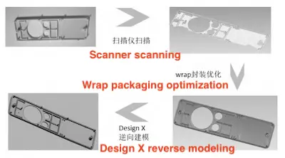
Figure 3 Reverse process
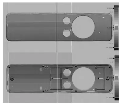
Figure 4 Deviation analysis

Figure 3 Reverse process

Figure 4 Deviation analysis
3. Mold Structure Design
3.1 Parting Surface Design
For the upper cover of the air conditioner remote control, the parting line position is roughly determined through slope analysis, and the neutral surface is defined by the front or rear mold during demolding. The four through holes in the model are formed using the front mold method, which helps avoid burrs and flash, improving the surface quality of the product.
3.2 Design of Cavity Quantity and Arrangement
This product requires an annual output of 500,000 pieces, classifying it as mass production. The appearance surface must be free of obvious defects, with a surface roughness of Ra=0.8. The precision level is MT3, and after comprehensive consideration, one mold with two cavities was chosen, with a 180-degree central symmetry arrangement.
3.3 Casting System Design
3.3.1 Main Runner Design
The main runner connects the injection machine nozzle to the branch runner. The main runner is typically designed with a taper of 1–2° to facilitate demolding. Additionally, the main runner should be kept as short as possible to reduce condensate volume and save materials. For the upper cover of the air conditioner remote control, the main runner uses a gate sleeve design. The total length of the runner is 67.6 mm, with a nozzle radius of 11 mm, an upper end diameter of 3 mm, and a lower end diameter of 4.77 mm. The runner has a taper of 1.5°, and an M8 screw is used for positioning.
3.3.2 Branch Runner Design
Based on the one-mold, two-cavity arrangement and the flow characteristics of the PC, the branch runner's single-side length is set at 15.5 mm with a circular cross-section. A cold material well is designed to store excess material and ensure that the condensate entering the cavity meets the required temperature. This design improves product quality and reduces defects.
3.3.3 Gate Design
Since the upper cover of the air conditioner remote control is small, with a side wall thickness of 1.5 mm and high surface accuracy requirements, direct gates and point gates are not appropriate. Considering the model and mold structure, side gates are used.
3.4 Concave and Convex Mold Structure Design
The concave mold is responsible for forming the outer surface of the remote control cover, and the cavity primarily shapes the appearance of the plastic part. The upper surface of the plastic part is smooth and flat, with high surface quality requirements. The cavity uses an integral embedded structure with dimensions of 160 mm x 200 mm x 40 mm. The convex mold is responsible for forming the inner surface of the remote control. The upper surface of the plastic part is smooth and flat, with high surface quality requirements. The cavity uses an integral embedded structure with dimensions of 160 mm x 200 mm x 50 mm. Figures 5 and 6 show the concave and convex mold structures.
3.5 Determination of Mold Frame Model
A Plate Size: The depth of the concave mold is 40 mm. Since the concave mold is installed on the A plate, space must be reserved for the cooling water channel. After careful consideration, the thickness of the A plate is set at 70 mm.
B Plate Size: The thickness of the convex mold is 50 mm. During the mold forming process, the B plate bears most of the weight and must also accommodate space for the water channel. As a result, the strength requirement of the B plate is relatively high, and its thickness is set at 80 mm.
C Plate Size: The size of the C plate is mainly determined by the height and ejection stroke of the product. Generally, a 5–10 mm ejection distance should be reserved to facilitate easy removal of the product during demolding. Additionally, the ejection distance should not be too long to avoid increasing ejection time and reducing production efficiency. In summary, the height of the C plate is set at 90 mm, and the ejection distance is 40 mm.
Based on the dimensions of each plate and core, mold frame CI-2730-A70-B80-C90 is selected, with an overall size of 320 mm × 300 mm × 291 mm.
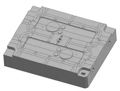
Figure 5 The concave mold structure
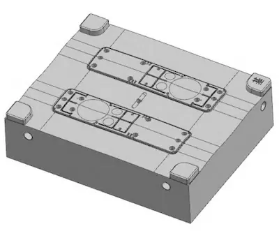
Figure 6 The convex mold structure
B Plate Size: The thickness of the convex mold is 50 mm. During the mold forming process, the B plate bears most of the weight and must also accommodate space for the water channel. As a result, the strength requirement of the B plate is relatively high, and its thickness is set at 80 mm.
C Plate Size: The size of the C plate is mainly determined by the height and ejection stroke of the product. Generally, a 5–10 mm ejection distance should be reserved to facilitate easy removal of the product during demolding. Additionally, the ejection distance should not be too long to avoid increasing ejection time and reducing production efficiency. In summary, the height of the C plate is set at 90 mm, and the ejection distance is 40 mm.
Based on the dimensions of each plate and core, mold frame CI-2730-A70-B80-C90 is selected, with an overall size of 320 mm × 300 mm × 291 mm.

Figure 5 The concave mold structure

Figure 6 The convex mold structure
3.6 Demolding Mechanism Design
Based on the product structure, the two boss columns are ejected by a sleeve, while the rest are ejected by pins. The interior of the air conditioner remote control cover contains more reinforcing ribs in the upper part and has a more complex structure, including three through-hole structures. This reduces the available contact area for ejection, so 4 large ejectors (5 mm) and 4 small ejectors (2.5 mm) are used in tandem. The lower part is ejected directly by 4 large ejectors.
3.7 Cooling System Design
The primary function of the cooling system is to remove the heat released when the melt solidifies, ensuring the condensate forms within an appropriate temperature range. An effective temperature control system minimizes plastic part deformation, which helps achieve better surface quality during molding. The cooling water channel diameter is set at 8 mm, with a circular distribution structure. Additionally, the cooling systems for the die and punch are designed separately to improve cooling efficiency.
3.8 Guide Pin and Guide Sleeve Design
A total of four guide pins and guide sleeves are designed for this mold. The material is SKD61, with a hardness of 54-58 HRC after quenching. The guide pins and guide sleeves work together to guide the mold during closing. They are evenly distributed in the four corners of the fixed template. The guide sleeve is installed on the fixed template, while the guide pin is installed on the movable template. Additionally, the guide pin has an oil groove for adding lubricating oil, which reduces friction and extends its service life.
3.9 Reset Mechanism Design
The function of the reset mechanism is to return the ejector pin to its initial position after the product is ejected. This design utilizes a rectangular spring to facilitate the reset of the ejector pin. The total length of the spring is 60 mm, with a preload of 10 mm. It has been verified that the compression ratio is within a reasonable range and ensures the reset of the ejector plate. The designed mold is illustrated in Figure 7.
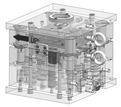
Figure 7 Three-dimensional diagram of the mold

Figure 7 Three-dimensional diagram of the mold
4. Selection of Injection Molding Machine Model
The selection scheme for this project determines the inner distance of the injection molding machine tie rod based on the mold frame size, ultimately establishing the injection molding machine model. The mold frame for the air conditioner remote control is CI type 2730, with dimensions of 320 mm × 300 mm × 291 mm. Based on the requirements for hanging the mold and the opening and closing stroke, the selected Haitian injection molding machine model is HTF86/TJ. In conjunction with the designed mold, the clamping force, maximum injection pressure, and mold opening stroke of the injection molding machine were further checked, all of which are within a reasonable range. Therefore, the selected HTF86/TJ injection molding machine fully meets the product injection molding requirements and fulfills the production requirements.
5. Conclusion
This design primarily redesigns the existing remote control cover and creates the mold. The software utilized includes Wrap, DesignX, and UG. It can also serve as a reference for companies engaged in the mass production of similar products, which holds significant practical value.
Related News
- Design of Two-stage Overmolding for Automobile Headlight Cover
- Research on Stamping of Complex Aerospace Sheet Metal Components (Part Two)
- Research on Stamping of Complex Aerospace Sheet Metal Components (Part one)
- Design of the Upper Cover of a Household Air Conditioner Remote Control
- The Mold Cavity of Overmolding Handheld Forehead Thermometer Casing
- Overmolding Handheld Forehead Thermometer Shells
- Defects of Overmolded Lampshades
- An Introduction to Overmolding
- Overmolding Lampshades For Car Headlights
- Deformation of Plastic Components
News
Advantages
Low Cost
Topper leverages an offshore plastic mold making plant with a lower cost structure in order to offer lower pricing than Topper's competitors.
High Quality
Quick Turnaround
Topper leverages an offshore plastic mold making plant with a lower cost structure in order to offer lower pricing than Topper's competitors.
High Quality
Topper is ISO 9001:2008 certified, and Topper processing quality systems ensure that your parts are the highest quality possible for your applications.
Quick Turnaround
Topper offers three different shipping methods, including next day air, to accommodate your timing and budget requirements.
Online Quotes
Topper interactive online quotation system provides instant quotes for plastic mold making, injection molding, CNC machining and die casting.
Online Quotes
Topper interactive online quotation system provides instant quotes for plastic mold making, injection molding, CNC machining and die casting.

