Optimization of Stamping Process for Automobile Structural Parts (Part One)
Abstract: The design of automotive structural parts is a process of continuous improvement and optimization. After the product information is sent to the process department, the process engineer needs to analyze the forming characteristics of the parts, final quality of the product, the strength of the mold, feasibility of the trimming process, and production cost and then propose modification suggestions, and the product department will form the final product data according to the optimization suggestions to optimize the production process, improve the quality of parts, and reduce costs.
Automobile structural parts are the parts that form the automobile skeleton, affect the stability and safety of the automobile structure, and support various components of the automobile. In the development of automotive products, there are a large number of structural parts and their building relationships are relatively complex, which have become an important factor in the accuracy and strength of the vehicle body and the development cost of the entire vehicle.
After the product design is completed, the process design department conducts process planning and computer-aided engineering (CAE analysis) for the stamping parts, generally asking questions and proposing risks from the aspects of formability, quality assurance of parts, the strength of molds and feasibility of the trimming process, production costs, etc., which will be fed back to the product design department in the form of ECR(engineering change request). The product design department will modify and optimize the product data to reduce the cost of mold development, optimize the production process, and improve the quality of the whole vehicle. As shown in the following, it is the general process of process design of auto parts.
The design process of auto parts:
Product data
↓
Stamping process planning
↓
CAE analysis
↓
ECR feedback
↓
Product data
↓
DL design
↓
Structural drawing design
Analysis of formability
1) If the filleted corner radius of the stamping part is too small, it will cause the partial part to be too sharp, and the thinning rate of the part will exceed the limit, which will cause the part to crack. In general, the filleted corner radius of the inner panel structure of the automobile should be greater than 3 mm as far as possible to avoid increasing the number of molds; the filleted corner radius of the partial convex hull or pit should be greater than 8 mm. The size of the specific filleted corner radius is related to the material and shape of the part. We can calculate the thinning rate of the part through CAE analysis of the digital model of the product; confirm whether there will be cracking at the filleted corner, and select a reasonable filleted corner radius that meets the forming requirements for the part according to the analysis result.
As shown in Figure 1, it is the digital model of the parts of the top cover beam of a certain car model. In the SE data stage, the radius of the filleted corner of the counterbore on the upper part of the beam is 5 mm. After CAE analysis, the root of this boss is rounded during the drawing process, which exceeds the forming limit. The filleted corner has the risk of cracking. After preliminary analysis, increasing the filleted corner radius to 7mm can eliminate the cracking. Through the overall troubleshooting of the digital model, the quality of the digital model is optimized.

Figure 1 Optimization of the filleted corners 5 and 7
The drawing depth or height of the hole flanging should be within a reasonable range. Pay special attention to the partial part with high drawing depth or flanging holes. The excessive thinning rate can easily cause cracking. You can confirm whether cracking will easily occur through the CAE analysis software to improve the structure of the part. Set features that reduce the drawing depth or change the forming process, optimize the flow characteristic of materials to avoid cracking. The optimization process of flanging holes of mounting plates of a part is shown in Figure 2.
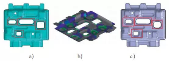
Figure 2 Optimization of flanging holes of mounting plates of a part
Holes 1#, 2#, 3# and 4# were originally flanging holes with a flanging height of 5 mm. The process is punching-flanging (hole). According to the analysis, the flanging hole has a high height, and there are cracks around the hole. After product optimization, the punching and flanging structure of 1# and 4# is changed to a stepped hole structure, and the process is changed to form the boss first. Rounded corners at the bottom of the edge and the surrounding filleted corner in 2#, 3# are enlarged, and the height of the flanging is changed from 3 mm to 1 mm, which can improve the cracking of the flanging hole of the part.
The stamping parts have negative angles. In the stamping and forming process, the parts will be difficult to demold and cannot be taken out normally, or additional processes need to be added. Therefore, the parts should have a certain draft angle, and the parts with a deep drawing depth or the draft angle of high-strength board parts should be appropriately increased. In the stage of digital model analysis, first, determine the stamping direction of the part through product process analysis. When the product is processed in the selected stamping direction, if there is a negative angle between the molded surface of parts and the stamping direction, optimization should be carried out to avoid the part not being taken from the mold due to negative angles, resulting in an increase in the process or the complexity of the mold structure.
Automobile structural parts are the parts that form the automobile skeleton, affect the stability and safety of the automobile structure, and support various components of the automobile. In the development of automotive products, there are a large number of structural parts and their building relationships are relatively complex, which have become an important factor in the accuracy and strength of the vehicle body and the development cost of the entire vehicle.
After the product design is completed, the process design department conducts process planning and computer-aided engineering (CAE analysis) for the stamping parts, generally asking questions and proposing risks from the aspects of formability, quality assurance of parts, the strength of molds and feasibility of the trimming process, production costs, etc., which will be fed back to the product design department in the form of ECR(engineering change request). The product design department will modify and optimize the product data to reduce the cost of mold development, optimize the production process, and improve the quality of the whole vehicle. As shown in the following, it is the general process of process design of auto parts.
The design process of auto parts:
Product data
↓
Stamping process planning
↓
CAE analysis
↓
ECR feedback
↓
Product data
↓
DL design
↓
Structural drawing design
Analysis of formability
1) If the filleted corner radius of the stamping part is too small, it will cause the partial part to be too sharp, and the thinning rate of the part will exceed the limit, which will cause the part to crack. In general, the filleted corner radius of the inner panel structure of the automobile should be greater than 3 mm as far as possible to avoid increasing the number of molds; the filleted corner radius of the partial convex hull or pit should be greater than 8 mm. The size of the specific filleted corner radius is related to the material and shape of the part. We can calculate the thinning rate of the part through CAE analysis of the digital model of the product; confirm whether there will be cracking at the filleted corner, and select a reasonable filleted corner radius that meets the forming requirements for the part according to the analysis result.
As shown in Figure 1, it is the digital model of the parts of the top cover beam of a certain car model. In the SE data stage, the radius of the filleted corner of the counterbore on the upper part of the beam is 5 mm. After CAE analysis, the root of this boss is rounded during the drawing process, which exceeds the forming limit. The filleted corner has the risk of cracking. After preliminary analysis, increasing the filleted corner radius to 7mm can eliminate the cracking. Through the overall troubleshooting of the digital model, the quality of the digital model is optimized.
Figure 1 Optimization of the filleted corners 5 and 7
The drawing depth or height of the hole flanging should be within a reasonable range. Pay special attention to the partial part with high drawing depth or flanging holes. The excessive thinning rate can easily cause cracking. You can confirm whether cracking will easily occur through the CAE analysis software to improve the structure of the part. Set features that reduce the drawing depth or change the forming process, optimize the flow characteristic of materials to avoid cracking. The optimization process of flanging holes of mounting plates of a part is shown in Figure 2.
Figure 2 Optimization of flanging holes of mounting plates of a part
Holes 1#, 2#, 3# and 4# were originally flanging holes with a flanging height of 5 mm. The process is punching-flanging (hole). According to the analysis, the flanging hole has a high height, and there are cracks around the hole. After product optimization, the punching and flanging structure of 1# and 4# is changed to a stepped hole structure, and the process is changed to form the boss first. Rounded corners at the bottom of the edge and the surrounding filleted corner in 2#, 3# are enlarged, and the height of the flanging is changed from 3 mm to 1 mm, which can improve the cracking of the flanging hole of the part.
The stamping parts have negative angles. In the stamping and forming process, the parts will be difficult to demold and cannot be taken out normally, or additional processes need to be added. Therefore, the parts should have a certain draft angle, and the parts with a deep drawing depth or the draft angle of high-strength board parts should be appropriately increased. In the stage of digital model analysis, first, determine the stamping direction of the part through product process analysis. When the product is processed in the selected stamping direction, if there is a negative angle between the molded surface of parts and the stamping direction, optimization should be carried out to avoid the part not being taken from the mold due to negative angles, resulting in an increase in the process or the complexity of the mold structure.

Related News
- Design of Two-stage Overmolding for Automobile Headlight Cover
- Research on Stamping of Complex Aerospace Sheet Metal Components (Part Two)
- Research on Stamping of Complex Aerospace Sheet Metal Components (Part one)
- Design of the Upper Cover of a Household Air Conditioner Remote Control
- The Mold Cavity of Overmolding Handheld Forehead Thermometer Casing
- Overmolding Handheld Forehead Thermometer Shells
- Defects of Overmolded Lampshades
- An Introduction to Overmolding
- Overmolding Lampshades For Car Headlights
- Deformation of Plastic Components
News
Advantages
Low Cost
Topper leverages an offshore plastic mold making plant with a lower cost structure in order to offer lower pricing than Topper's competitors.
High Quality
Quick Turnaround
Topper leverages an offshore plastic mold making plant with a lower cost structure in order to offer lower pricing than Topper's competitors.
High Quality
Topper is ISO 9001:2008 certified, and Topper processing quality systems ensure that your parts are the highest quality possible for your applications.
Quick Turnaround
Topper offers three different shipping methods, including next day air, to accommodate your timing and budget requirements.
Online Quotes
Topper interactive online quotation system provides instant quotes for plastic mold making, injection molding, CNC machining and die casting.
Online Quotes
Topper interactive online quotation system provides instant quotes for plastic mold making, injection molding, CNC machining and die casting.
Follow Us
Topper is a professional plastic mold manufacturer in China, our injection molding service covers all walks of life, including medical, electronics, auto parts, appliance, etc.
Contact Us
Topper Plastic Mold Co., Ltd.
Address: No. 879, Xiahe Road, Xiamen, Fujian, China
Tel: 0086-592-5819200
Email: sales@plastic-mold.com
Website: https://www.plastic-mold.com
Copyright © China Plastic Mold Co., Ltd. Robot Arm for Injection Molding. Privacy Policy | Terms of Service | Sitemap
Website Design & Support: jeawin.com