Research on Stamping of Complex Aerospace Sheet Metal Components (Part Two)
On this page
2. Finite Element Analysis of Stamping
Pam-Stamp2G finite element simulation software is now used for forming feasibility analysis and mold design optimization. The unit system used in the simulation analysis is mm-kg-ms-kN-GPa, and the stamping form establishes a single-action tensile model based on actual production conditions.
2.1 Material Model Development
To characterize the 2024-O aluminum-clad plate, a university was commissioned to test the mechanical properties of the raw materials used for production. The test results are provided in Table 1, and the true stress-strain curves for the plate in three directions are displayed in Figure 2.
Table 1 Mechanical property parameters of 2024-O aluminum alloy sheet
Table 1 Mechanical property parameters of 2024-O aluminum alloy sheet
| Property | Rolling Direction | 0° | 45° | 90° |
| Elastic Modulus (GPa) | 70.3 | 69.9 | 70.4 | |
| Yield Strength (MPa) | 66.5 | 65.0 | 65.0 | |
| Tensile Strength (MPa) | 177.5 | 166.5 | 164.5 | |
| Uniform Elongation (%) | 13.1 | 19.3 | 14.7 | |
| Elongation at Break (%) | 22.8 | 23.6 | 18 | |
| Thickness Anisotropy Coefficient | 0.719 | 0.653 | 0.715 | |
| Strain Hardening Coefficient (MPa) | 311.5 | 300.5 | 280.5 | |
| Strain Hardening Index | 0.213 | 0.225 | 0.198 | |
| Poisson's Ratio | 0.32 | 0.33 | 0.33 |
2.2 Establishment and Analysis of Geometric Model
In single-action stretching, the punch is typically fixed on the lower die seat, while the blank holder is supported by the lower ejector pin and fits tightly against the pressing die to secure the sheet. In this study, the model is built using a concave surface, and the punch and blank holder are generated in Pam-Stamp2G from the solid surface. Given the significant impact of blank holder surface characteristics on forming results, three geometric models were designed: a regular sheet with a flat blank holder, a regular sheet with a profiled blank holder, and a sheet with a profiled blank holder that includes holes.
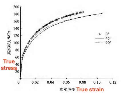
Figure 2 True stress-true strain curves of raw material stretching in different rolling directions

Figure 2 True stress-true strain curves of raw material stretching in different rolling directions
2.2.1 Regular Sheet with Flat Blank Holder
The geometric model of a regular sheet with a flat blank holder is shown in Figure 3. The concave surface is based on the product's three-dimensional model, with an additional process allowance of 20 mm. A flat blank holder is designed, incorporating continuous, uniformly spaced draw ribs around the stamping metal part.
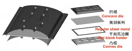
Figure 3 Geometric model of flat blank holder and regular sheet
The results of the calculations for the regular sheet with a flat blank holder are shown in Figure 4. Figure 4a presents a color-coded diagram of material thickness reduction in the formed part. As shown, the profile’s forming condition is satisfactory, with a thickness of approximately 0.1 mm at the reinforcing rib position. Material thinning reached 0.368 mm at both ends of the ribs, with a maximum reduction of 30.67%.
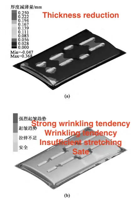
(a) Material thinning cloud map (b) Forming safety threshold cloud map
Figure 4 Forming results of the plane blank holder ring regular sheet
Figure 4b displays a color-coded map of the part's safety thresholds. As seen in Figure 4b, most of the surface stress conditions are within acceptable limits, with no cracking, but there is a significant tendency toward wrinkling between adjacent ribs. Despite repeated adjustments to parameters such as blank holder force, draw rib shape and spacing, and drawing depth, this issue persists. Thus, this forming method is not the optimal processing solution for this part.

Figure 3 Geometric model of flat blank holder and regular sheet
The results of the calculations for the regular sheet with a flat blank holder are shown in Figure 4. Figure 4a presents a color-coded diagram of material thickness reduction in the formed part. As shown, the profile’s forming condition is satisfactory, with a thickness of approximately 0.1 mm at the reinforcing rib position. Material thinning reached 0.368 mm at both ends of the ribs, with a maximum reduction of 30.67%.

(a) Material thinning cloud map (b) Forming safety threshold cloud map
Figure 4 Forming results of the plane blank holder ring regular sheet
Figure 4b displays a color-coded map of the part's safety thresholds. As seen in Figure 4b, most of the surface stress conditions are within acceptable limits, with no cracking, but there is a significant tendency toward wrinkling between adjacent ribs. Despite repeated adjustments to parameters such as blank holder force, draw rib shape and spacing, and drawing depth, this issue persists. Thus, this forming method is not the optimal processing solution for this part.
2.2.2 Curved Blank Holder for Regular Sheet
The geometric model of the curved blank holder for the regular sheet is shown in Figure 5. The concave surface is derived from the product’s three-dimensional model, with an extended process allowance of 20 mm. The blank holder surface is offset in the stamping direction and further extended by 60–80 mm. Continuous, uniformly spaced draw ribs are added around the part.
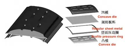
Figure 5 Geometric model of curved blank holder and regular sheet
The calculation results for the curved blank holder and regular sheet model are shown in Figure 6. Fig. 6a illustrates the material thickness reduction in the part, indicating good formability. Material thinning at the rib position ranges from approximately 0.05 to 0.1 mm, with a maximum thinning of 0.335 mm at both rib ends, representing a 27.92% reduction. Compared with the flat blank holder, the curved blank holder reduces maximum material thinning during part forming. However, material thinning is more pronounced at the rib position, especially in the fillet area at the rib's base. Figure 6b presents a safety map for part forming. As shown, most of the surface stress conditions are acceptable, with no visible cracking. However, cracking occurs in the fillet area at the rib’s base, and a strong wrinkling tendency persists between adjacent ribs. Despite multiple adjustments to relevant parameters, these issues remain, indicating that further optimization of the forming scheme is needed.
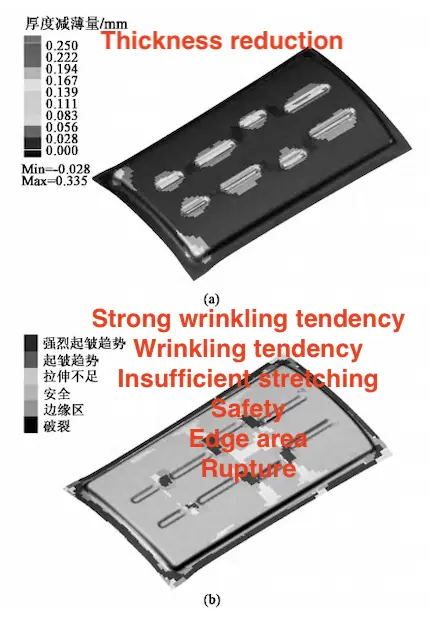
(a) Material thinning nephogram (b) Forming safety threshold nephogram
Figure 6 Forming result of curved blank holder and regular sheet

Figure 5 Geometric model of curved blank holder and regular sheet
The calculation results for the curved blank holder and regular sheet model are shown in Figure 6. Fig. 6a illustrates the material thickness reduction in the part, indicating good formability. Material thinning at the rib position ranges from approximately 0.05 to 0.1 mm, with a maximum thinning of 0.335 mm at both rib ends, representing a 27.92% reduction. Compared with the flat blank holder, the curved blank holder reduces maximum material thinning during part forming. However, material thinning is more pronounced at the rib position, especially in the fillet area at the rib's base. Figure 6b presents a safety map for part forming. As shown, most of the surface stress conditions are acceptable, with no visible cracking. However, cracking occurs in the fillet area at the rib’s base, and a strong wrinkling tendency persists between adjacent ribs. Despite multiple adjustments to relevant parameters, these issues remain, indicating that further optimization of the forming scheme is needed.

(a) Material thinning nephogram (b) Forming safety threshold nephogram
Figure 6 Forming result of curved blank holder and regular sheet
2.2.3 Sheet with Hole in the Curved Blank Holder
The geometric model of the perforated sheet with a curved blank holder, as shown in Figure 7, still utilizes a curved blank holder. A prefabricated drawing hole is positioned at the original opening of the part to enhance material flow and reduce the risk of cracking. The calculation results for the perforated sheet with a curved blank holder model are shown in Figure 8. Figure 8a shows a thickness thinning nephogram of the part. The overall forming condition is favorable, with material thinning occurring only at the rib end, where maximum thinning reaches 0.273 mm, representing a 22.75% reduction. Figure 8b displays a forming safety threshold nephogram. The part experiences uniform and adequate force distribution, with no signs of cracking. Wrinkling between adjacent ribs has been resolved. While some wrinkling appears around the prefabricated hole during drawing, this area falls within the waste zone according to the part outline. Compared to the first two methods, this scheme fully stretches the effective area of the part, significantly reducing springback after forming and resulting in the best overall forming effect.
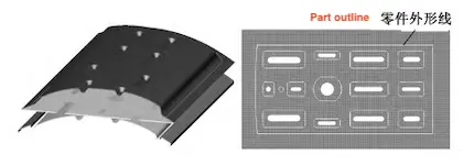
Figure 7 Geometric model of curved blank holder and perforated sheet
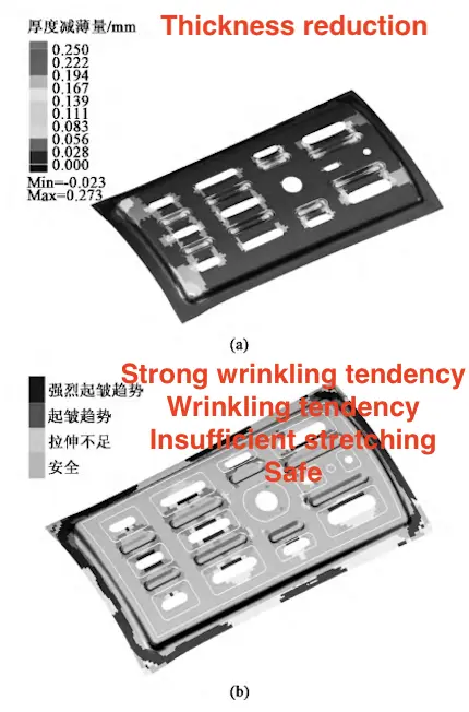
Figure 8 Thickness thinning nephogram of the part

Figure 7 Geometric model of curved blank holder and perforated sheet

Figure 8 Thickness thinning nephogram of the part
3. Design of Part Forming Tooling and Process Test
Based on the finite element analysis results, the forming scheme using a sheet with a profiled pressure ring and a hole was selected, and the stamping tooling was designed accordingly, as shown in Figure 9. The sheet is milled according to a two-dimensional blanking digital model to create the stamping blank. When the blank is formed on the stamping equipment, its movement is restricted by eight positioning blocks on the pressure ring. After stamping, the parts need to be cut using a five-axis, three-dimensional cutting machine. Therefore, positioning holes aligned with the milling fixture are created during forming, so two punching devices are designed on the die as inserts.
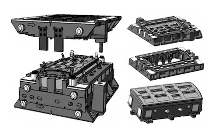

Figure 9 Craft equipment of stamping
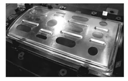
Figure 10 Stamping part
After forming and cutting, the parts exhibit slight edge rebound compared to those formed with the original drop die. Partial repair of the stamping tooling reduced the degree of rebound, allowing for part delivery readiness. Currently, parts processed with the tooling are shown in Figure 10, and batch production has been achieved. The part processing steps were reduced from 16 to 9, eliminating procedures like pickling and multiple annealing in heat treatment stations. The production cycle was reduced from 11 days to 1.5 days, greatly improving production efficiency. In the drop forming process, the parts experienced severe wrinkling and poor surface quality. The stamping process minimizes part wrinkling and significantly reduces springback by incorporating draw ribs, resulting in improved surface quality.
4. Conclusion
This study focuses on the complex frame reinforcement used in aviation, employing finite element simulation software to evaluate the feasibility of a new forming process and designing the forming tooling based on the simulation results. This new high-quality and efficient forming process successfully replaces the outdated method, proving viable for actual production. It provides a reference for optimizing similar part-forming processes and advancing the modernization of traditional sheet metal production.
Related News
- Design of Two-stage Overmolding for Automobile Headlight Cover
- Research on Stamping of Complex Aerospace Sheet Metal Components (Part Two)
- Research on Stamping of Complex Aerospace Sheet Metal Components (Part one)
- Design of the Upper Cover of a Household Air Conditioner Remote Control
- The Mold Cavity of Overmolding Handheld Forehead Thermometer Casing
- Overmolding Handheld Forehead Thermometer Shells
- Defects of Overmolded Lampshades
- An Introduction to Overmolding
- Overmolding Lampshades For Car Headlights
- Deformation of Plastic Components
News
Advantages
Low Cost
Topper leverages an offshore plastic mold making plant with a lower cost structure in order to offer lower pricing than Topper's competitors.
High Quality
Quick Turnaround
Topper leverages an offshore plastic mold making plant with a lower cost structure in order to offer lower pricing than Topper's competitors.
High Quality
Topper is ISO 9001:2008 certified, and Topper processing quality systems ensure that your parts are the highest quality possible for your applications.
Quick Turnaround
Topper offers three different shipping methods, including next day air, to accommodate your timing and budget requirements.
Online Quotes
Topper interactive online quotation system provides instant quotes for plastic mold making, injection molding, CNC machining and die casting.
Online Quotes
Topper interactive online quotation system provides instant quotes for plastic mold making, injection molding, CNC machining and die casting.

